An electric fence system consists of an electric fence energiser , a fence wire or combination of wires supported on insulators, fixed on posts. These together with the EARTH system, form a pulsed high voltage OPEN LOOP with the animal being the completing link. The effectiveness of the fence is the shock, in both the meanings of the word.
THE MAIN POINTS ARE:
- Effective energiser.
- Good effective grounding of the fence energiser.
- The conductivity of the ground on which the animal stands.
- Good insulation of the `live 'conductor.
- Type of wire used. The thicker the gauge the better. Galvanised Steel, High Tensile or Polywire (conductive wires in a plastic `wire '.
An electric fence is a less-than-ideal environment on which to conduct electricity. Along the course of the average fence there are many conditions that will divert or impede the flow of electricity. Collectively, these conditions are known as the `fence load '.
Weeds or vegetation growing on the fence line is the most common culprit contributing to a heavy fence load. Green plants draw voltage and amperage from the fence to earth. Other circumstances can rob the fence of voltage and amperage. Cracked or broken insulators, or insulators of a poor design will allow electricity to leak to the fence post and down to earth. Sagging or broken wires can contact un-insulated wires or the ground. Wet weather will magnify all of these problems. When enough conditions exist to draw all of the electricity produced by the energiser from the fence, the fence is said to be `shorted out '.
Rusty wire, poor splices, or wire of insufficient diameter to carry the flow of voltage and amperage also contribute to fence load. These problems do not draw voltage and amperage to earth, but they do impede the flow of electricity along the fence, contributing to the fence load.
Even the length of the fence contributes to the fence load. The longer the fence, the less ability (or greater capacitance) it has to store the energy supplied by the Energiser. On very long fences, capacitance can become a major contributor to the fence load.
Proper construction with quality components, installing an adequately powered energiser, a proper earth installation and good management practices are the key to keeping fence load under control.
Inadequate earthing is the most common failure in electric fence operation. See the Earth Return System section.
In areas where heavy snow and ice are common, you may need to make additional earthing measures. Most people do not realise that snow or rainwater will not conduct electricity. Frozen ground also reduces the flow of current. When animals are to be left out in electric fenced areas in frozen snowy conditions you can improve the electric fence function by running a live/earth return system.
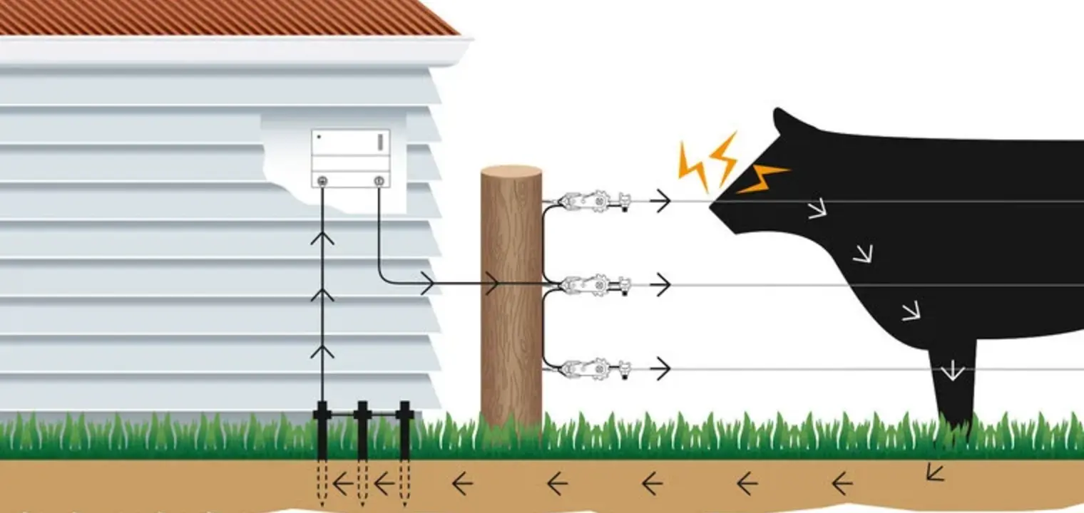
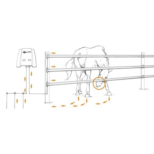
How Electric Fencing WorksAs can be seen from the diagram below, the higher powered the fencer energiser is, the thicker the energy line, therefore there is more energy available when leakages such as foliage , etc., touches the line to sustain the voltage and thus the distance. It must be said that there is an upper limit to this power (Energy) for SAFETY. All Gallagher energisers are built to the highest safety standards. The average pulse duration is one hundred millionths of a second with at least 1 second between pulses. |
 |
Does an electric fence have to make a complete loop?The short answer is: no. For an electric fence to be properly installed it should not be a closed loop. When an animal touches the electric fence, this should be the missing link in the loop for the animal to get the shock. The loop can also be formed by vegetation touching the fence. This results in the fence leaking power. The eventual shock the animal gets from the fence is determined by the amount of power 'leaked' from the fence between the animal and the energiser. This is also the reason why a stronger energiser is recommended when the fence is placed in high vegetation. |
 |
Energiser operation:
Battery Energisers OperationBasically the battery runs an oscillator (fly-back converter), which in turn steps up the battery voltage to around 500 volts. This is rectified and this DC voltage is used to charge up the reservoir capacitor. Depending on the size of the capacitor and the DC voltage determines the stored energy (volts' x capacitance 12 = Stored Joules). This energy is then discharged through the Pulse Transformer primary via the thyristor switch at a rate of not more than once per second. A resistor and capacitor network achieve this timing. The Pulse transformer is a step up device, which is normally of a 1:10 ratio giving approximately a pulse of 7000 volts on the fence line. |
 |
Mains Energisers OperationThe Gallagher mains energiser works on the same principle except the mains voltage is doubled, dispensing with need for an oscillator circuit, using a voltage doubler network which in turn charges up the reservoir capacitor to the required voltage (approximately 700volts). The timing circuits and triggering principles remain the same as the battery units. The resulting high voltage pulse is applied to the pulse transformer and then to the fence line and when the animal touches the fence the animal completes the circuit via the ground and the animal receives a shock. Consequently the ground is just an important part of the fence as the fence line itself. |
|

TV and telephone interference
Gallagher energisers do not cause interference. This is normally caused by bad joints, leaking insulation or vegetation touching the fence line. If you are experiencing interference please follow the checklist below:
- The Energiser Earth system must be sufficient.
- The Energiser Earth System must be 10 m away from the mains supply, safety Earth and buried water pipes.
- The energiser MUST NOT be connected to the mains supply safety earth or to the water supply pipes.
- The mains power supply plugs and sockets for the radio and the energiser must be in good working order. No Loose Connections.
- The energiser earth cable must not touch buildings, which can act as a broadcast aerial.
- The energiser's ground system should be at least 10 m away from radios and buried telephone wires.
- Avoid running the electric fence line parallel to power or telephone lines.
- Use only top quality Gallagher insulators. Sparking inside cracked or poor quality insulators causes interference.
- Vegetation touching the fence line close to the radio can also cause sparking and therefore interference.
To locate sparking caused by leakage, faulty joins, broken wires or faulty insulators, walk the fence line with a transistor radio tuned off station on the AM band on high volume. The clicking will get louder as the fault is approached.
If all of the above have been implemented and there is still a problem, then carry out the following test to locate the fault.
- Run the energiser with both the fence and earth leads disconnected. If there is no click on the radio the interference is coming from the fence line or earth. If there is still a click then the fault is in the energiser or in the mains power supply connections.
- To find out if the fault is in the energiser or the mains power supply, carry out the following tests:
-
- Disconnect the earth and fence leads from the energiser terminals and have someone at the offending radio to count the clicks.
- Switch the energiser on and just before the fifth click (or any other prearranged number of clicks), quickly remove the plug.
- If this click is not heard, then the interference is being transmitted by the mains power supply.
Try another power socket, check the radio plug wiring and if still not corrected, install a simple earth and aerial for the radio. If the last click was still heard on the radio, the problem is with the energiser itself and it should be returned to Gallagher with a note explaining the problem.
Browning off vegetation
We do not recommend Electro Plastic wire/tape for fences over 800 metres of single strand. If using 2 or 3 parallel lines of Electro Plastic wire/tape then connect lines together at both ends to fence up to 1000 metres. For greater distances we recommend galvanised or high tensile steel wire.
Installation of mains energiser
These units (all current mains energisers) are designed to be fitted indoors.
For Mains Energisers: mount the energiser on a wall, under shelter & out of reach of children, near a mains switched supply. Do not handle PVC cords when the temperature is below +5 degrees centigrade.
Install the Earth Spike at least 10m from any safety earth to a depth of at least 1m in continuously damp soil. Using Double Insulated HT Cable, clamp its wire to the Earth Spike and insert the other end of the cable to the EARTH (Black) terminal on the energiser. DO NOT connect to the Mains supply Earth. See the earthing sub-section. In dry and poor EARTH conditions it may be necessary to add additional Earth Spikes at approximately 3m intervals. Using Double Insulated HT cable connect the Live, normally Red, (Units with a Blue terminal: this is a half power terminal) Fence line output terminal to the fence line. Connect the mains lead to the power supply and switch on.
The red neon on the right indicates there is power entering the energiser: The red neon on the left will pulse at approximately one pulse per second, indicating the energiser is working correctly. Energisers with an Earth leakage-monitor will indicate the condition of the Fence Line. Particularly useful in areas of high vegetation.
In areas of very poor earth conditions it may be necessary to run an earth returns system. Make sure you plan your fence layout well. For maximum efficiency use a multi-wire system consisting of at least 3 wires connected in parallel. Avoid stony, rough or steep areas if at all possible. Run out the wires between the end posts using suitable insulators and tension the wires until there is only slight sag. Connect all live wires together at the beginning and end of each fence section.
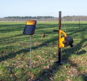
Installation of battery energiser
The installation of battery energisers is very similar to that of the mains, except that they can be placed anywhere in the field as required.
Make sure the energiser is switched OFF before connecting to the battery.
Position the energiser near to the fence Line. Push the Earth Spike or Stand into moist ground.
For 12 volt energisers the (RED) Positive and (BLACK) Negative crocodile clips are connected to the 12v wet leisure type battery. (A car battery is not recommended as they are not designed to be deeply discharged).
The Fence (Red) output terminal is connected to the fence line
The Earth (Black) output terminal is connected to the Earth Spike. (A 1 metre galvanised steel spike is recommended. Part number ES2). For short distances the earth lead may be connected to the stand. See our earthing advice section
Switch the Energiser ON. The 12-volt energisers will flash GREEN, at about one pulse per second. Indicating that they are working correctly. When the battery requires recharging it will go RED as well. If the battery is connected the wrong way round a buzzer will sound.
The 6-volt and 9 volt energiser, the light (if fitted) will flash bright RED indicating that the energiser is working correctly. If the RED light stays ON, check the battery. The RED crocodile clip goes to the fence line and the GREEN crocodile clip goes to the Earth Spike.
In areas of very poor earth conditions it may be necessary to run an earth returns system. (See Diagram of Live/Earth Wire System above) Make sure you plan your fence layout well. For maximum efficiency use a multi-wire system consisting of at least 3 wires connected in parallel. Avoid stony, rough or steep areas if at all possible.
Run out the wires between the end posts using suitable insulators and tension the wires until there is only slight sag.
Connect all live wires together at the beginning and end of each fence section.
General electric fencing tips
Regularly check the fence line for vegetation growing over the fence line of fallen branches, as this will reduce the voltage on the line.
Always use HT/G double insulated cable in buildings and under gates. Never use ordinary house cable as it is only rated at 600 volts and may cause leakage to earth.
Please note that the fence line does not need to form a complete loop. The animal completes the loop.
Where there is more than one line of live wires or tape, these can be joined together at regular intervals.
Connect all live wires together at the beginning and end of each fence section.
Connect the fence sections under gateways rather than over, using double insulated HTG cable run in a protective plastic pipe at least 25cm deep. Make sure the ends of the pipe are turned down to prevent water entering. For more information on Gateways go to the Electric Fencing and Gates section.
Earth return system
The earthing system is an integral part of your energiser's performance. As with all energisers there must be a return path through the ground and Earth Spike back to the energiser in order to complete the loop. The Earth Spikes must be totally independent from the household/domestic earthing arrangements and at least 10 metres away from an electricity supply earth rod where an earth leakage trip is employed.
Always bear in mind that all electrical circuits must form a complete loop from the positive (live) to the negative (earth) is just as much part of the circuit as the fence line and the animal is the missing link that completes the loop.
Vegetation will also complete the loop causing the output voltage of the energiser to drop. Therefore it is very important to keep any growth on the line to a minimum to ensure the animal receives the maximum shock from the Energiser.
An effective EARTH system is three 1 metre steel spikes (Part No ES2) driven fully into the soil approximately 3 metres apart and joined together and if possible buried in the ground with 2.5mm galvanised steel cable. This then connected to the earth terminal of the energiser with high voltage lead-out cable. Always try to install the earth system in a permanently damp area. If this is not possible, water the ground around the Earth Spikes in dry weather conditions.
For particularly poor earth conditions (sand, peat, gravel, very dry soil, snow or frozen ground) it is possible to increase the earth efficiency by:
- increasing the number of Earth Spikes.
- by running an earth return wire in parallel to the fence line and connecting it to Earth Spikes at regular intervals.
Testing your earth system
To test an Earth Spike installation, firstly short out the live fence line to ground, either with a metal stake or by laying the fence line on the ground for about 100 metres and at least 30 metres away from the energiser.
- Switch the energiser ON.
Measure the voltage between the GROUND and the Earth Spike with a meter (Part No. P35). If this is above 200 volts the earth installation is inefficient. Check the connections or increase the number of Earth Spikes.
If you get a shock from the Earth Spike before you short the fence line, then there is a poor Earth AND possibly a fault on the fence line as well. (Check for vegetation on the line or faulty insulators).
Electric Fencing and gates
Connect all live wires together at the beginning and end of each fence section.
Connect the fence sections under gateways rather than over, using double insulated HTG cable run in a protective plastic pipe at least 25cm deep. Make sure the ends of the pipe are turned down to prevent water entering.
Connect each end of the cable securely to each fence section. Do not use spring type electric gates to get power across to the other section as this may cause arcing and burn out the connectors of the gate handles.
A temporary Tape Gate can be installed at the end or beginning of a temporary fence system. When the gate is opened the gate is disconnected from the power and the gate becomes dead and will not affect the live fence if dropped to the ground.
A Bungee Type electro rope gate would also be suitable for this system.
Gateways and major changes of fence direction are ideal places to put cut out switches for maintenance and fault finding.
Electric Fence heights
To use as a guide, here is a selection of suggested electric fence heights for permanent systems for certain animals.
- Badgers: 3 Wires:
Wire 1 - 100mm, Wire 2 - 330mm, Wire 3 - 580mm - Cattle: 2 Wires:
Wire 1 - 600mm, Wire 2 - 920mm - Cats, Dogs, Foxes: 4 Wires:
Wire 1 - 110mm, Wire 2 - 270mm, Wire 3 - 430mm, Wire 4 - 580mm - Deer:* 4 Wires:
Wire 1 - 460mm, Wire 2 - 1020mm, Wire 3 - 1480mm, Wire 4 - 1880mm - Heron: 2 Wires:
Wire 1 - 200mm, Wire 2 - 350mm - Horses: 3 Wires:
Wire 1 - 460mm, Wire 2 - 1020mm, Wire 3 - 1480mm - Otter, Mink: 3 Wires:
Wire 1 - 70mm, Wire 2 - 140mm, Wire 3 - 210mm - Pigs: 2 Wires:
Wire 1 - 230mm, Wire 2 - 535mm - Rabbits: 4 Wires: Wire 1 - 110mm, Wire 2 - 200mm, Wire 3 - 290mm, Wire 4 - 410mm
- Sheep: 4 Wires:
Wire 1 - 225mm, Wire 2 - 460mm, Wire 3 - 550mm, Wire 4 - 920mm
These are just suggestions based on our own experience and research. The height of your electric fence can vary of course, depending on your own preference and also the breed of animal you're trying to control. If in doubt, it is always better to add an extra line.
It can be of benefit to have a selection of electrified fencing in a field along with normal stock fencing in order to train naturally curious young animals for later when moving the animals to a fully electrified enclosure.
* Deer tend to 'measure' a fence before jumping. To prevent this 'measuring' process, you could attach an electric wire to an existing fence at a height of 1.8 m using a long offset bracket. When the deer tries to 'measure' the fence it receives a shock and moves away. Deer cannot judge three dimensionally and must 'measure' first.
Another common procedure that may increase the effectiveness of electric fences is to 'bait' a wire, in the case of deer, at 1.2 m with peanut butter to attract, shock and therefore deter the animal.
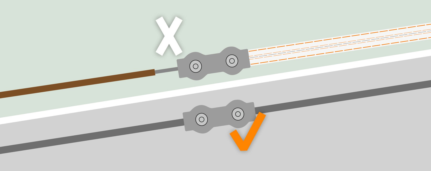
Connecting wire, rope & tapes
Lightning protection
Lightning strikes can damage energisers. Damage can be minimised by disconnecting the energiser from the fence line and disconnecting it from the power supply during electrical storms.
A P74 Lightning arrestor kit is recommended to minimise damage to your energiser. Lightning always finds the easiest path to ground. Therefore the ground system of the lightning arrestor must be as good as or better than the energiser ground.
The choke can be made quite simply and causes a blocking effect for the extremely high voltage of the lightning so that it jumps the silicon carbide discs in the arrestor and is diverted to ground.
In areas where lightning is a major problem it would be advantageous to have additional arrestors dispersed over the farm in damp areas.
Safety requirements and regulations
- Electric fences shall be installed and operated so that they cause no electrical hazard to persons, animals or their surroundings.
- Electric fence constructions, which are likely to lead to entanglement of animals or persons, shall be avoided.
- An electric fence shall not be supplied from more than one energiser or from independent fence circuits of the same energiser.
- The gap between two separate electric fences with different energisers shall be at least 2 m.
- If this gap is to be closed, this should be effected by means of a electrically non conductive material.
- Barbed or razor wire shall not be electrified by an energiser.
- Any part of an electric fence which is installed along a public path or highway shall be identified by warning plates securely fastened to the fence posts or firmly clamped to the fence wires at intervals recommended to be of approximately 10 metres to 50 metres, but not exceeding 90 metres.
- Thewarning signs shall be at least 100 mm x 200 mm. The background colour of both sides shall be yellow.
- The inscription shall be black and shall be the substance of TAKE CARE - ELECTRIC FENCE.
- The inscription shall be indelible, inscribed on both sides and have a height of at least 25 mm.
- Except for low output battery operated energisers, the energiser earth electrode shall penetrate the ground to a depth of at least 1m.
- Connecting leads that are run inside buildings shall be effectively insulated from the earth structural parts of the building. This may be achieved by using double insulated high voltage cable HT or HTG Cable.
- Connecting leads that are run underground shall be run in a conduit of insulating material.
- Care shall be taken to avoid damage to the connecting leads due to the effects of animal hooves or tractor wheels sinking into the ground.
- Connecting leads shall not be installed in the same conduit as the mains supply wiring, communication cables or data cables.
- Connecting leads and electric fence wires shall not cross above overhead power or communication lines.
- Crossings with overhead cables shall be avoided wherever possible. If such a crossing cannot be avoided, it shall be made underneath the power line and as nearly as possible at right angles to it.
If connecting leads and electric fences are installed near an overhead power line the clearances shall be:
1. Power Line Voltage: Under 1000 volts - Clearance: 3 Metres
2. Power Line Voltage: 1000 - 33,000 volts - Clearance: 4 Metres
3. Power Line Voltage: Over 33,000 volts - Clearance: 8 Metres
If connecting leads and electric fence wires are installed near an overhead power line, their height above ground shall not exceed 2 m. This height applies either side of the orthogonal projection of the outermost conductors of the power line on the ground surface, for a distance of - 2 m for power lines not exceeding 1000 V - 15 m for power lines exceeding 1000 V.
A distance of 10 m shall be maintained between the energiser Earth Spike and any other earthing system such as the power supply system protective earth or the telecommunication system earth.
Electric fences intended for deterring birds, household pet containment or training animals such as cows need only be supplied from low output energisers to obtain satisfactory and safe performance.
In electric fences intended for deterring birds from roosting on buildings, no electric fence wire shall be connected to the Earth Spike.
A warning plate, as described earlier, shall be fitted to every point where persons may gain ready access to the conductors.
A non-electrified fence incorporating barbed wire or razor wire may be used to offset electrified wires of an electric animal fence. The supporting devices for the electrified wires shall be constructed so as ensure these wires are positioned at a minimum distance of 150 mm from the vertical plane of the non electrified wires. The barbed / razor wire shall be earthed at regular intervals.
Where an electric animal fence crosses a public pathway, a non-electrified gate shall be incorporated in the electric fence at that point or a crossing by means of stiles shall be provided.
At any such crossing, the adjacent electrified wires shall carry warning plates as described earlier.